CVAT provides several editor-level modes that change how the annotation workspace behaves.
These modes control what actions are available to the user, which tools can be used, and how objects can be
created or modified.
Use this section to understand when to switch modes and how each mode supports a specific step of the annotation workflow.
1 - Single shape
Guide to annotating tasks using Single Shape mode
The CVAT Single Shape annotation mode accelerates the annotation process and enhances
workflow efficiency for specific scenarios.
By using this mode you can label objects with a chosen annotation shape and label when an image
contains only a single object. By eliminating the necessity to select tools from the sidebar
and facilitating quicker navigation between images without
the reliance on hotkeys, this feature makes the annotation process significantly faster.
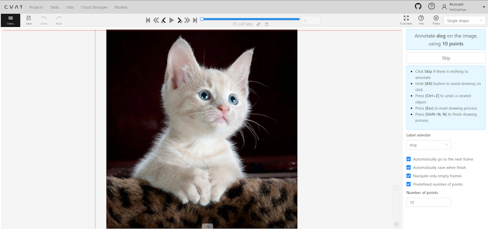
A set of controls in the interface of the Single Shape annotation mode may vary depending on different settings.
Images below displays the complete interface, featuring all available fields;
as mentioned above, certain fields may be absent depending on the scenario.
For instance, when annotating
with rectangles, the Number of points field will not appear, and if annotating a single class,
the Labels selector will be omitted.
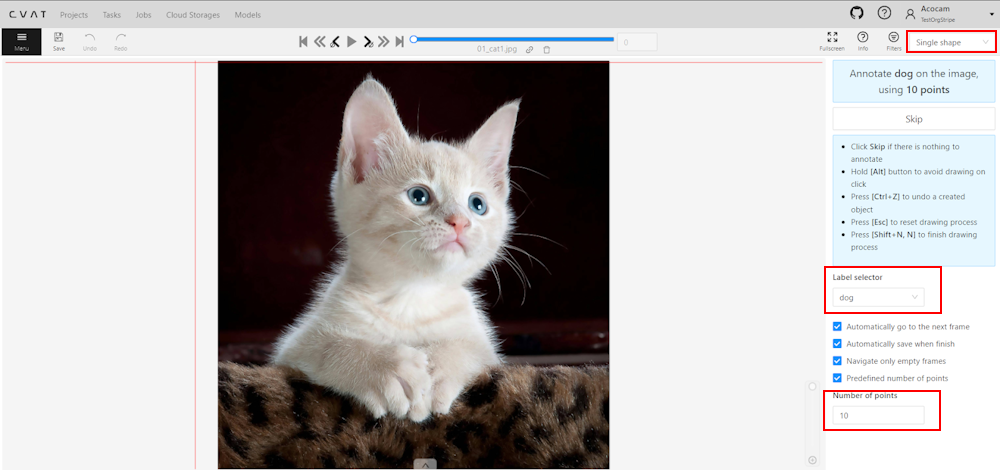
To access Single Shape mode, open the job, navigate to the
top right corner, and from the drop-down menu, select Single Shape.
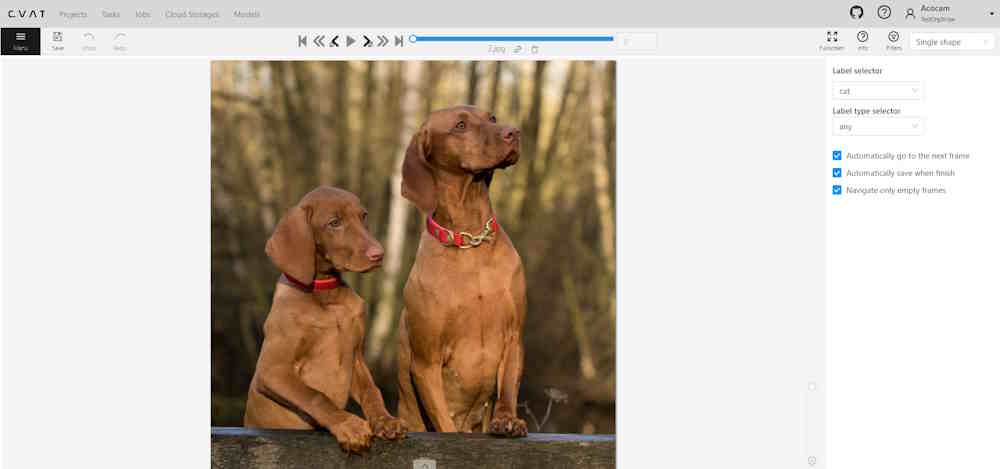
The interface will be different if the shape type was set to Any in the label Constructor:
The Single Shape annotation mode has the following fields:
Feature
Explanation
Prompt for Shape and Label
Displays the selected shape and label for the annotation task, for example: “Annotate cat on the image using rectangle”.
Skip Button
Enables moving to the next frame without annotating the current one, particularly useful when the frame does not have anything to be annotated.
List of Hints
Offers guidance on using the interface effectively, including: - Click Skip for frames without required annotations. - Hold the Alt button to avoid unintentional drawing (e.g. when you want only move the image). - Use the Ctrl+Z combination to undo the last action if needed. - Use the Esc button to completely reset the current drawing progress.
Label selector
Allows for the selection of different labels (cat, or dog in our example) for annotation within the interface.
Label type selector
A drop-down list to select type of the label (rectangle, ellipse, etc). Only visible when the type of the shape is Any.
Options to Enable or Disable
Provides configurable options to streamline the annotation process, such as: - Automatically go to the next frame. - Automatically save when finish. - Navigate only empty frames. - Predefined number of points - Specific to polyshape annotations, enabling this option auto-completes a shape once a predefined number of points is reached. Otherwise, pressing N is required to finalize the shape.
Number of Points
Applicable for polyshape annotations, indicating the number of points to use for image annotation.
Annotating in Single Shape mode
To annotate in Single Shape mode, follow these steps:
Open the job and switch to Single Shape mode.
Annotate the image based on the selected shape.
For more information on shapes, see
Annotation Tools.
(Optional) If the image does not contain any objects to annotate,
click Skip at the top of the right panel.
Submit your work.
Query parameters
Also, we introduced additional query parameters, which you may append to
the job link, to initialize the annotation process and automate workflow:
For a better understanding of how Single Shape mode operates,
we recommend watching the following tutorial.
2 - Track mode
Usage examples and basic operations available during annotation in track mode.
Usage examples:
Create new annotations for a sequence of frames.
Add/modify/delete objects for existing annotations.
Edit tracks, merge several rectangles into one track.
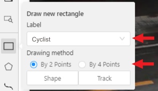
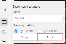
Like in the Shape mode, you need to select a Rectangle on the sidebar,
in the appearing form, select the desired Label and the Drawing method.
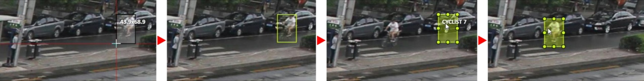
Creating a track for an object (look at the selected car as an example):
Create a Rectangle in Track mode by selecting Track.
In Track mode, the rectangle will be automatically interpolated on the next frames.
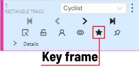
The cyclist starts moving on frame #2270. Let’s mark the frame as a key frame.
You can press K for that or select the star button (see the screenshot below).
If the object starts to change its position, you need to modify the rectangle where it happens.
It isn’t necessary to change the rectangle on each frame, simply update several keyframes
and the frames between them will be interpolated automatically.
Let’s jump 30 frames forward and adjust the boundaries of the object. See an example below:
After that the rectangle of the object will be changed automatically on frames 2270 to 2300:
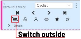
When the annotated object disappears or becomes too small, you need to
finish the track. You have to choose Outside Property, shortcut O.
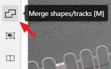
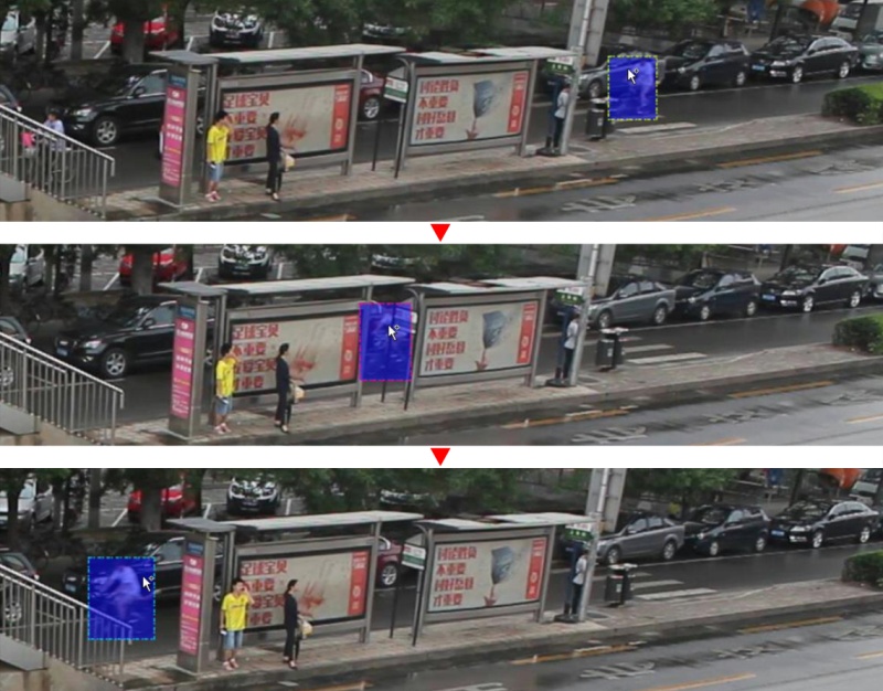
If the object isn’t visible on a couple of frames and then appears again,
you can use the Merge feature to merge several individual tracks
into one.
Create tracks for moments when the cyclist is visible:
Select Merge button or press key M and select on any rectangle of the first track
and on any rectangle of the second track and so on:
Select Merge button or press M to apply changes.
The final annotated sequence of frames in Interpolation mode can
look like the clip below:
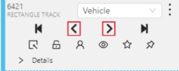
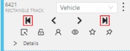
Shapes that were created in the track mode, have extra navigation buttons.
These buttons help to jump to the previous/next keyframe.
The button helps to jump to the initial frame and to the last keyframe.
You can use the Split function to split one track into two tracks:
3 - Attribute annotation mode
Usage examples and basic operations available in attribute annotation mode.
In this mode, you can edit attributes with fast navigation between objects and frames using a keyboard.
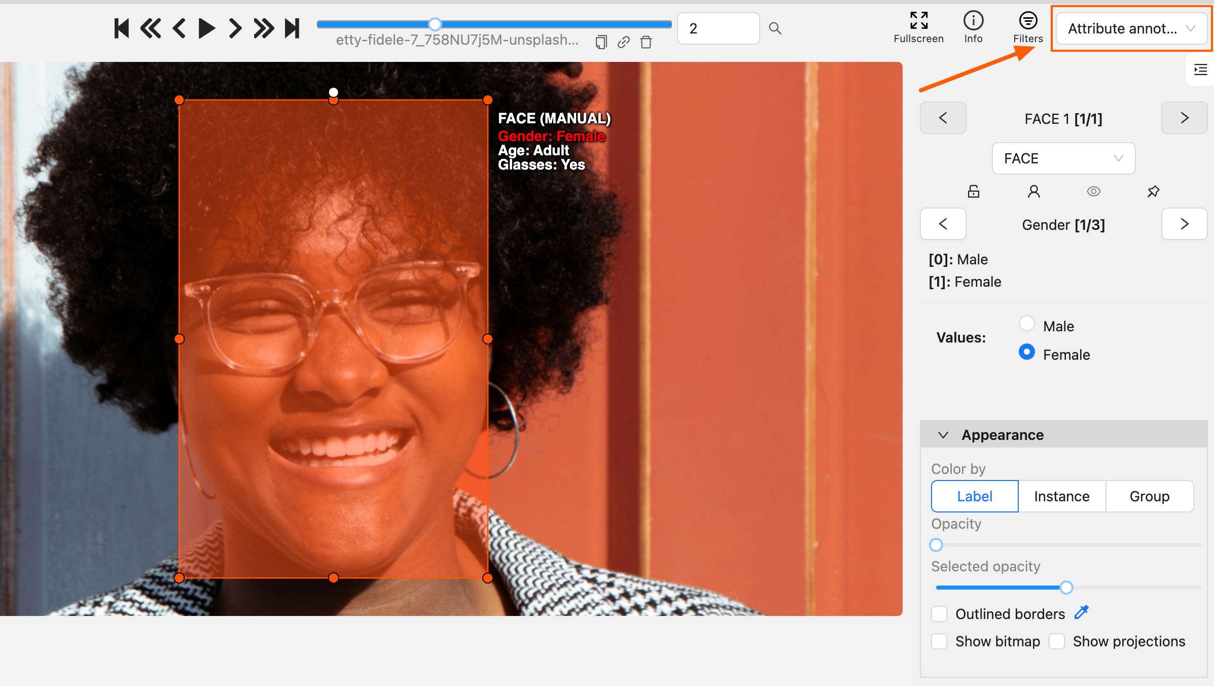
Open the drop-down list in the top panel and select Attribute annotation.
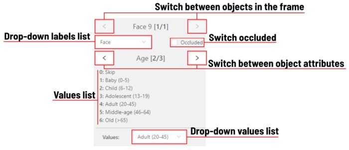
In this mode, objects panel change to a special panel:
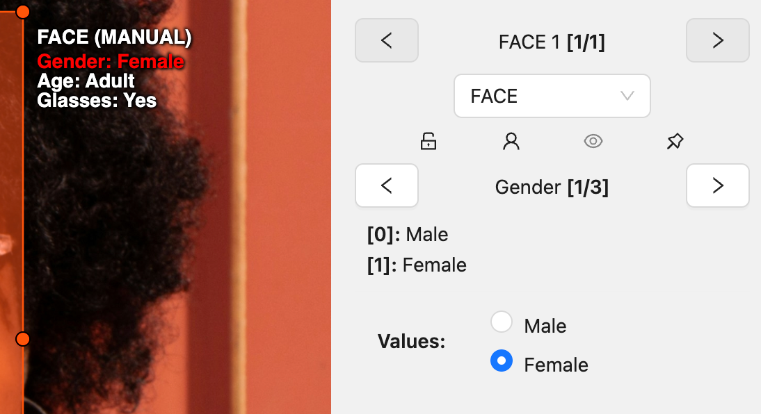
The active attribute will be red. In this case, it is gender. Look at the bottom side panel to see all possible
shortcuts for changing the attribute. Press key 2 on your keyboard to assign a value (female) for the attribute
or select from the drop-down list.
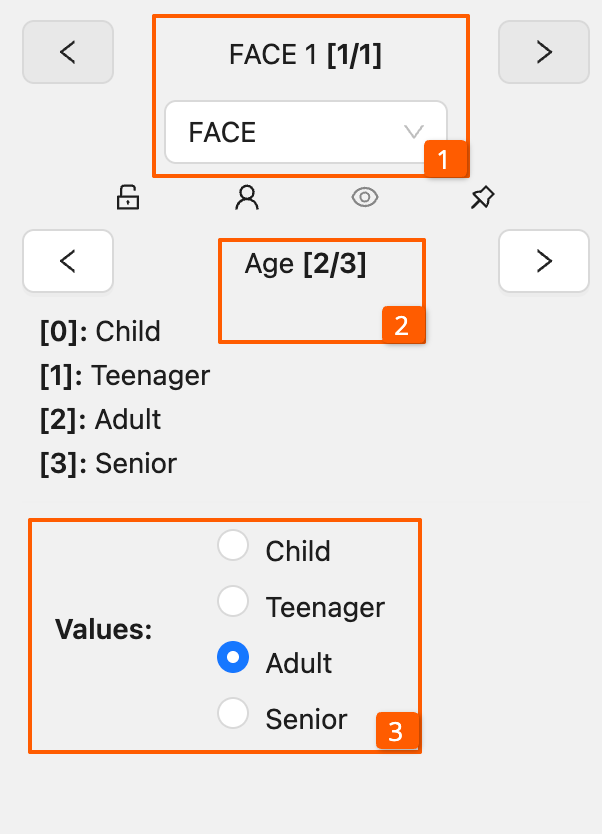
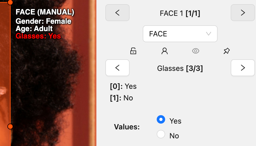
Press Up Arrow/Down Arrow on your keyboard or select the buttons in the UI to go to the next/previous
attribute. In this case, after pressing Down Arrow you will be able to edit the Age attribute.
Use Right Arrow/Left Arrow keys to move to the previous/next image with annotation.
To display all the hot keys available in the attribute annotation mode, press F2.
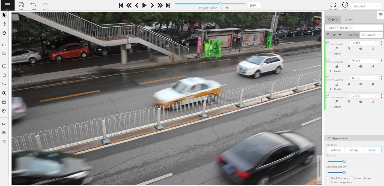
It is possible to handle lots of objects on the same frame in the mode.
It is more convenient to annotate objects of the same type. In this case you can apply
the appropriate filter. For example, the following filter will
hide all objects except person: label=="Person".
To navigate between objects (person in this case),
use the following buttons switch between objects in the frame on the special panel:
or shortcuts:
Tab — go to the next object
Shift+Tab — go to the previous object.
In order to change the zoom level, go to settings (press F3) in the workspace tab and set the value Attribute annotation mode (AAM) zoom margin in px.
4 - 3D object annotation
Overview of basic operations available when annotating 3D objects.
Use the 3D Annotation tool for labeling 3D objects and scenes, such as vehicles, buildings, landscapes, and others.
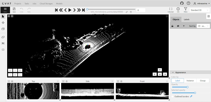
The 3D annotation canvas looks like the following:
Note
If you added contextual images to the dataset, the canvas will include them.
For more information, consult Contextual images
For information on the available tools, consult
Controls sidebar.
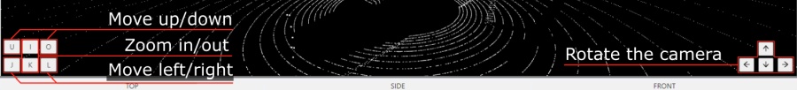
You can navigate, using the mouse, or navigation keys:
You can also use keyboard shortcuts to navigate:
Action
Keys
Camera rotation
Shift + Arrow (Up, Down, Left, Right)
Left/Right
Alt+J/ Alt+L
Up/down
Alt+U/ Alt+O
Zoom in/ou
Alt+K/ Alt+I
Annotation with cuboids
There are two options available for 3D annotation:
Shape: for tasks like object detection.
Track: uses interpolation to predict the position of objects in subsequent frames.
A unique ID will be assigned to each object and maintained throughout the sequence of images.
Annotation with shapes
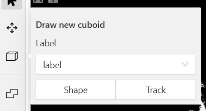
To add a 3D shape:
On the objects pane, select Draw new cuboid >
select the label from the drop-down list > Shape.
The cursor will be followed by a cuboid.
Place the cuboid on the 3D scene.
Use projections to adjust the cuboid.
Click and hold the left mouse button to edit the label shape on the projection.
(Optional) Move one of the four points to change the size of the cuboid.
(Optional) To rotate the cuboid, select the middle point
and then drag the cuboid up/down or to left/right.
Tracking with cuboids
To track with cuboids:
On the objects pane, select Draw new cuboid >
select the label from the drop-down list > Track.
The cursor will be followed by a cuboid.
Place the cuboid on the 3D scene.
Use projections to adjust the cuboid.
Select and hold the left mouse button to edit the label shape on the projection.
(Optional) Move one of the four points to change the size of the cuboid.
(Optional) To rotate the cuboid, click on the middle point
and then drag the cuboid up/down or to left/right.
Move several frames forward. You will see the cuboid you’ve added in frame 1.
Adjust it, if needed.
Repeat to the last frame with the presence of the object you are tracking.
For more information about tracking, consult Track mode.
As well as 2D-task objects, 3D-task objects support the ability to change appearance, attributes,
properties and have an action menu. Read more in
objects sidebar section.
Moving an object
If you hover the cursor over a cuboid and press Shift+N, the cuboid will be cut,
so you can paste it in other place (double-click to paste the cuboid).
Copying
As well as in 2D task you can copy and paste objects by Ctrl+C and Ctrl+V,
but unlike 2D tasks you have to place a copied object in a 3D space (double click to paste).
Image of the projection window
You can copy or save the projection-window image by left-clicking on it and selecting a “save image as” or “copy image”.
Cuboid orientation
The feature enables or disables the display of cuboid orientation arrows in the 3D space.
It is controlled by a checkbox located in the appearance block. When enabled, arrows representing
the cuboid’s axis orientation (X - red, Y - green, Z - blue) are displayed, providing a visual reference
for the cuboid’s alignment within the 3D environment. This feature is useful for understanding the spatial
orientation of the cuboid.
Cuboid size input
The size input feature allows users to manually specify the dimensions of a cuboid in the 3D space.
This feature is accessible through the objects sidebar - details panel, where you can input precise
values for the width, height, and length (X - width, Y - height, Z - length) of the cuboid.
By entering these values, the cuboid’s size is adjusted accordingly to its orientation, providing
greater control and accuracy when annotating objects in 3D tasks.
5 - Annotation with tags
It is used to annotate frames, tags are not displayed in the workspace.
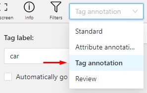
Before you start, open the drop-down list in the top panel and select Tag annotation.
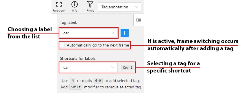
The objects sidebar will be replaced with a special panel for working with tags.
Here you can select a label for a tag and add it by clicking on the Plus button.
You can also customize hotkeys for each label.
If you need to use only one label for one frame, then enable the Automatically go to the next frame
checkbox, then after you add the tag the frame will automatically switch to the next.
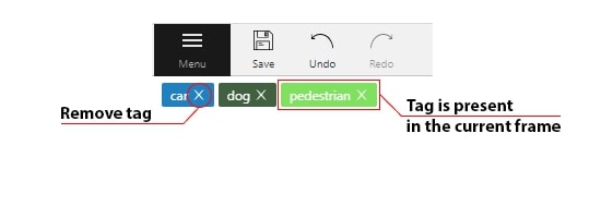
Tags will be shown in the top left corner of the canvas. You can show/hide them in the settings.