This section describes all shapes you can create in CVAT. Each shape type supports its own tools, editing options, and use cases.
Review these pages to choose the correct shape tool for your annotation task.
This is the multi-page printable view of this section. Click here to print.
This section describes all shapes you can create in CVAT. Each shape type supports its own tools, editing options, and use cases.
Review these pages to choose the correct shape tool for your annotation task.
To learn more about annotation using a rectangle, see the sections:
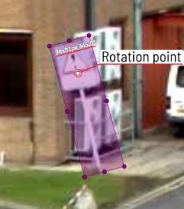
To rotate the rectangle, pull on the rotation point. Rotation is done around the center of the rectangle.
To rotate at a fixed angle (multiple of 15 degrees),
hold shift. In the process of rotation, you can see the angle of rotation.
It is an efficient method of bounding box annotation, proposed here. Before starting, you need to make sure that the drawing method by 4 points is selected.
Press Shape or Track for entering drawing mode. Click on four extreme points:
the top, bottom, left- and right-most physical points on the object.
Drawing will be automatically completed right after clicking the fourth point.
Press Esc to cancel editing.
Usage examples:
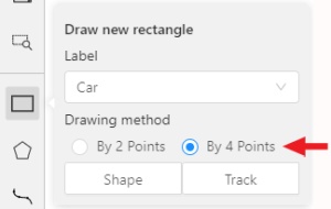
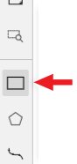
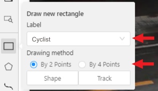
You need to select Rectangle on the controls sidebar:
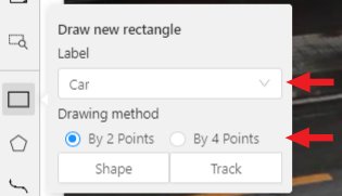
Before you start, select the correct Label (should be specified by you when creating the task)
and Drawing Method (by 2 points or by 4 points):
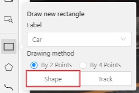
Creating a new annotation in Shape mode:
Create a separate Rectangle by selecting Shape.
Choose the opposite points. Your first rectangle is ready!
To learn more about creating a rectangle read here.
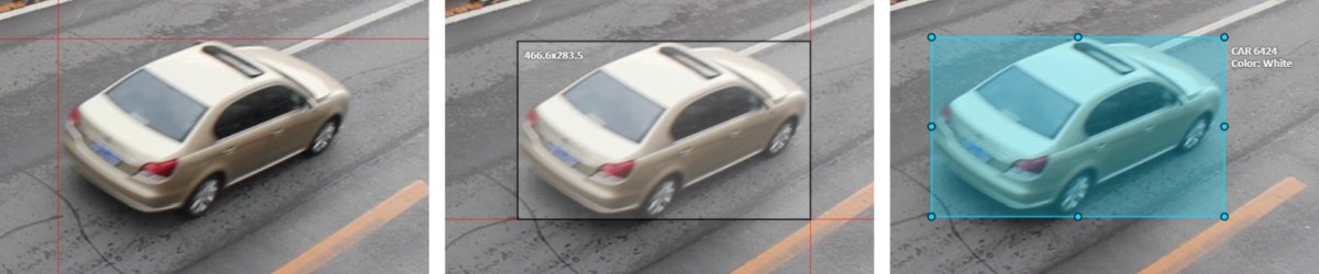
It is possible to adjust boundaries and location of the rectangle using a mouse.
The rectangle’s size is shown in the top right corner, you can check it by selecting any point of the shape.
You can also undo your actions using Ctrl+Z and redo them with Shift+Ctrl+Z or Ctrl+Y.
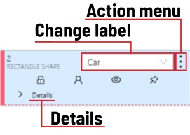
You can see the Object card in the objects sidebar or open it by right-clicking on the object.
You can change the attributes in the details section.
You can perform basic operations or delete an object by selecting on the action menu button.
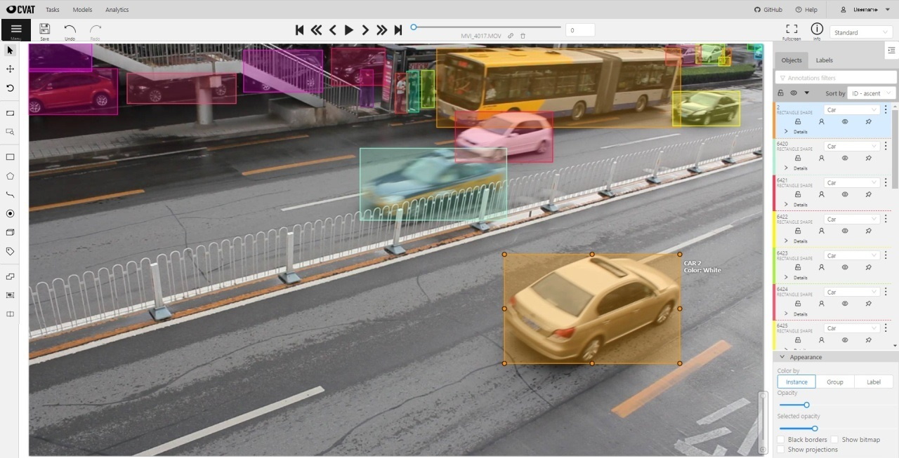
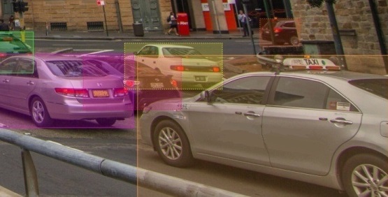
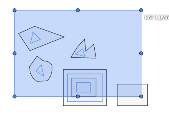
The following figure is an example of a fully annotated frame with separate shapes.
Occluded
Occlusion is an attribute used if an object is occluded by another object or
isn’t fully visible on the frame. Use Q shortcut to set the property
quickly.
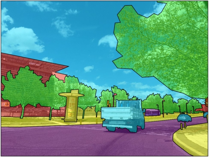
Example: the three cars on the figure below should be labeled as occluded.
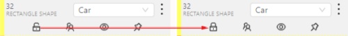
If a frame contains too many objects and it is difficult to annotate them
due to many shapes placed mostly in the same place, it makes sense
to lock them. Shapes for locked objects are transparent, and it is easy to
annotate new objects. Besides, you can’t change previously annotated objects
by accident. Shortcut: L.
It is used for semantic / instance segmentation.
Before starting, you need to select Polygon on the controls sidebar and choose the correct Label.
Shape to enter drawing mode.
There are two ways to draw a polygon: either create points by clicking or
by dragging the mouse on the screen while holding Shift.| Clicking points | Holding Shift+Dragging |
|---|---|
 |
 |
Shift isn’t pressed, you can zoom in/out (when scrolling the mouse
wheel) and move (when clicking the mouse wheel and moving the mouse), you can also
delete the previous point by right-clicking on it.Selected opacity slider in the Objects sidebar to change the opacity of the polygon.
You can read more in the
Objects sidebar section.N again or click the Done button on the top panel for completing the shape.Delete point
or clicking with pressed Alt key in the context menu.
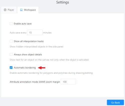
You can use auto borders when drawing a polygon. Using automatic borders allows you to automatically trace the outline of polygons existing in the annotation.
To do this, go to settings -> workspace tab and enable Automatic Bordering
or press Ctrl while drawing a polygon.
Start drawing / editing a polygon.
Points of other shapes will be highlighted, which means that the polygon can be attached to them.
Define the part of the polygon path that you want to repeat.
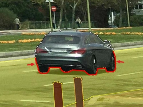
Click on the first point of the contour part.
Then click on any point located on part of the path. The selected point will be highlighted in purple.
Click on the last point and the outline to this point will be built automatically.
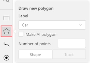
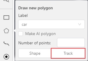
Besides, you can set a fixed number of points in the Number of points field, then
drawing will be stopped automatically. To enable dragging you should right-click
inside the polygon and choose Switch pinned property.
Below you can see results with opacity and black stroke:
If you need to annotate small objects, increase Image Quality to
95 in Create task dialog for your convenience.
To edit a polygon you have to click on it while holding Shift, it will open the polygon editor.
In the editor you can create new points or delete part of a polygon by closing the line on another point.
When Intelligent polygon cropping option is activated in the settings,
CVAT considers two criteria to decide which part of a polygon should be cut off during automatic editing.
If both criteria recommend to cut the same part, algorithm works automatically,
and if not, a user has to make the decision.
If you want to choose manually which part of a polygon should be cut off,
disable Intelligent polygon cropping in the settings.
In this case after closing the polygon, you can select the part of the polygon you want to leave.

You can press Esc to cancel editing.
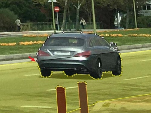
Polygons in the track mode allow you to mark moving objects more accurately other than using a rectangle.
To create a polygon in the track mode, click the Track button.
Create a polygon the same way as in the case of
Annotation with polygons.
Press N or click the Done button on the top panel to complete the polygon.
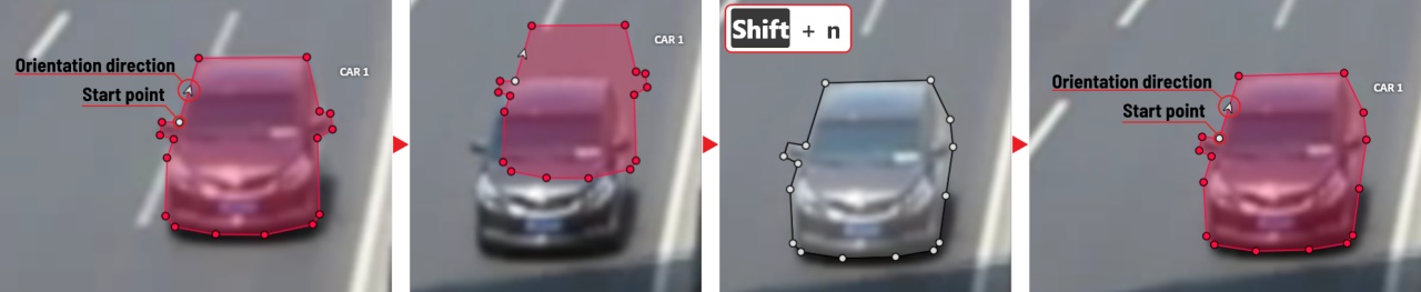
Pay attention to the fact that the created polygon has a starting point and a direction, these elements are important for annotation of the following frames.
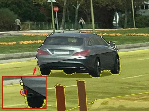
After going a few frames forward press Shift+N, the old polygon will disappear and you can create a new polygon.
The new starting point should match the starting point of the previously created polygon
(in this example, the top of the left mirror). The direction must also match (in this example, clockwise).
After creating the polygon, press N and the intermediate frames will be interpolated automatically.
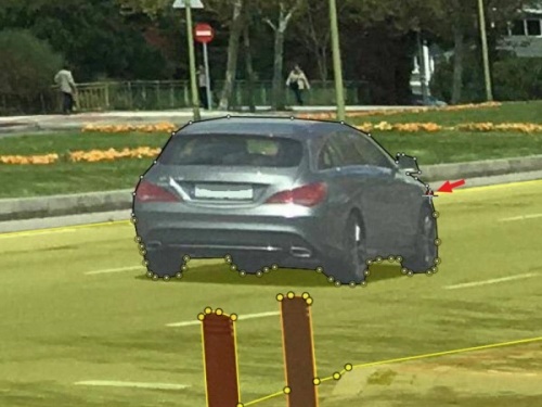
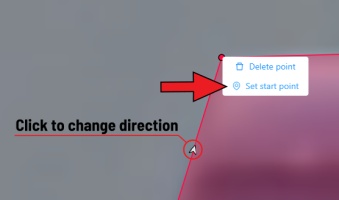
If you need to change the starting point, right-click on the desired point and select Set starting point.
To change the direction, right-click on the desired point and select switch orientation.
There is no need to redraw the polygon every time using Shift+N,
instead you can simply move the points or edit a part of the polygon by pressing Shift+Click.
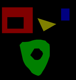
Currently, CVAT does not support cutting transparent holes in polygons. However, it is possible to generate holes in exported instance and class masks. To do this, one needs to define a background class in the task and draw holes with it as additional shapes above the shapes needed to have holes:
The editor window:
Remember to use z-axis ordering for shapes by [-] and [+, =] keys.
Exported masks:
Notice that it is currently impossible to have a single instance number for internal shapes (they will be merged into the largest one and then covered by “holes”).
There are several formats in CVAT that can be used to export masks:
Segmentation Mask (PASCAL VOC masks)CamVidMOTSICDARCOCO (RLE-encoded instance masks, guide)DatumaroAn example of exported masks (in the Segmentation Mask format):
Important notices:
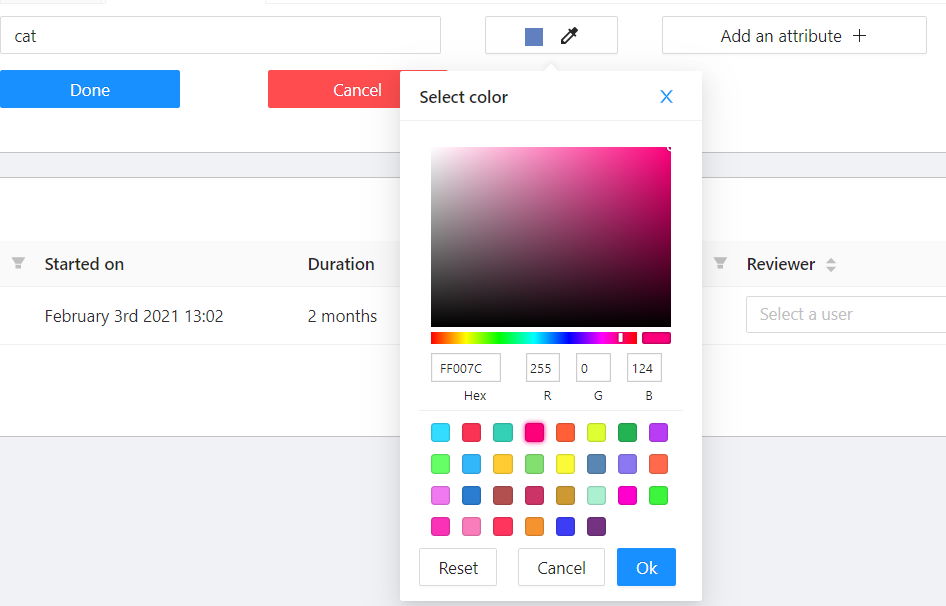
All the labels have associated colors, which are used in the generated masks. These colors can be changed in the task label properties:
Label colors are also displayed in the annotation window on the right panel, where you can show or hide specific labels (only the presented labels are displayed):
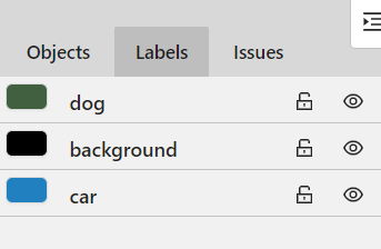
A background class can be:
background class with any color (has a priority, name is case-insensitive)To change background color in generated masks (default is black),
change background class color to the desired one.
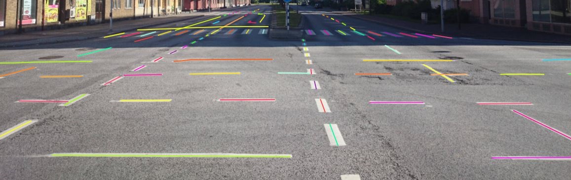
It is used for road markup annotation etc.
Before starting, you need to select the Polyline. You can set a fixed number of points
in the Number of points field, then drawing will be stopped automatically.
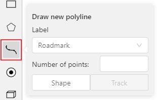
Click Shape to enter drawing mode. There are two ways to draw a polyline —
you either create points by clicking or by dragging a mouse on the screen while holding Shift.
When Shift isn’t pressed, you can zoom in/out (when scrolling the mouse wheel)
and move (when clicking the mouse wheel and moving the mouse), you can delete
previous points by right-clicking on it.
Press N again or click the Done button on the top panel to complete the shape.
You can delete a point by clicking on it with pressed Ctrl or right-clicking on a point
and selecting Delete point. Click with pressed Shift will open a polyline editor.
There you can create new points(by clicking or dragging) or delete part of a polygon closing
the red line on another point. Press Esc to cancel editing.
Usage examples:
Like in the Shape mode, you need to select a Rectangle on the sidebar,
in the appearing form, select the desired Label and the Drawing method.
Creating a track for an object (look at the selected car as an example):
Create a Rectangle in Track mode by selecting Track.
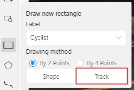
In Track mode, the rectangle will be automatically interpolated on the next frames.
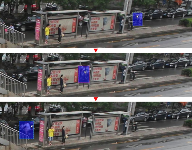
The cyclist starts moving on frame #2270. Let’s mark the frame as a key frame.
You can press K for that or select the star button (see the screenshot below).
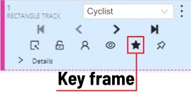
If the object starts to change its position, you need to modify the rectangle where it happens. It isn’t necessary to change the rectangle on each frame, simply update several keyframes and the frames between them will be interpolated automatically.
Let’s jump 30 frames forward and adjust the boundaries of the object. See an example below:
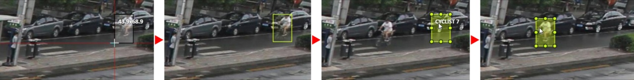
After that the rectangle of the object will be changed automatically on frames 2270 to 2300:
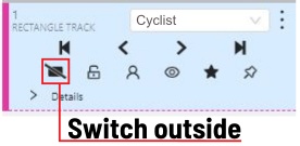
When the annotated object disappears or becomes too small, you need to
finish the track. You have to choose Outside Property, shortcut O.
If the object isn’t visible on a couple of frames and then appears again,
you can use the Merge feature to merge several individual tracks
into one.
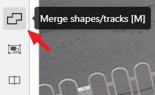
Create tracks for moments when the cyclist is visible:
Select Merge button or press key M and select on any rectangle of the first track
and on any rectangle of the second track and so on:
Select Merge button or press M to apply changes.
The final annotated sequence of frames in Interpolation mode can
look like the clip below:
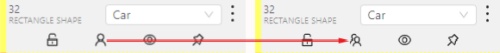
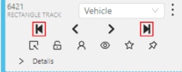
Shapes that were created in the track mode, have extra navigation buttons.
These buttons help to jump to the previous/next keyframe.
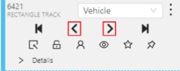
The button helps to jump to the initial frame and to the last keyframe.
You can use the Split function to split one track into two tracks:
It is used for face, landmarks annotation etc.
Before you start you need to select the Points. If necessary you can set a fixed number of points
in the Number of points field, then drawing will be stopped automatically.
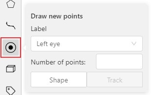
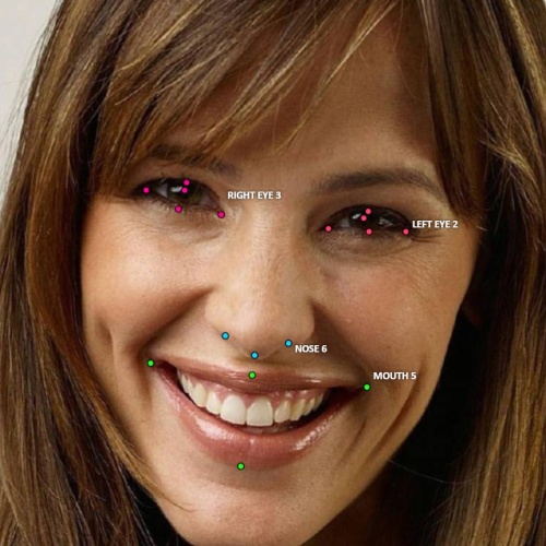
Click Shape to entering the drawing mode. Now you can start annotation of the necessary area.
Points are automatically grouped — all points will be considered linked between each start and finish.
Press N again or click the Done button on the top panel to finish marking the area.
You can delete a point by clicking with pressed Ctrl or right-clicking on a point and selecting Delete point.
Clicking with pressed Shift will open the points shape editor.
There you can add new points into an existing shape. You can zoom in/out (when scrolling the mouse wheel)
and move (when clicking the mouse wheel and moving the mouse) while drawing. You can drag an object after
it has been drawn and change the position of individual points after finishing an object.
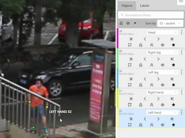
You can use linear interpolation for points to annotate a moving object:
Before you start, select the Points.
Linear interpolation works only with one point, so you need to set Number of points to 1.
After that select the Track.
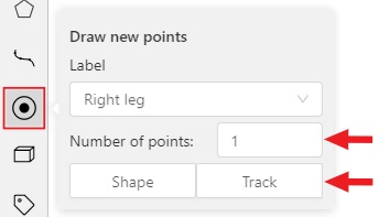
Click Track to enter the drawing mode left-click to create a point
and after that shape will be automatically completed.
Move forward a few frames and move the point to the desired position,
this way you will create a keyframe and intermediate frames will be drawn automatically.
You can work with this object as with an interpolated track: you can hide it using the Outside,
move around keyframes, etc.
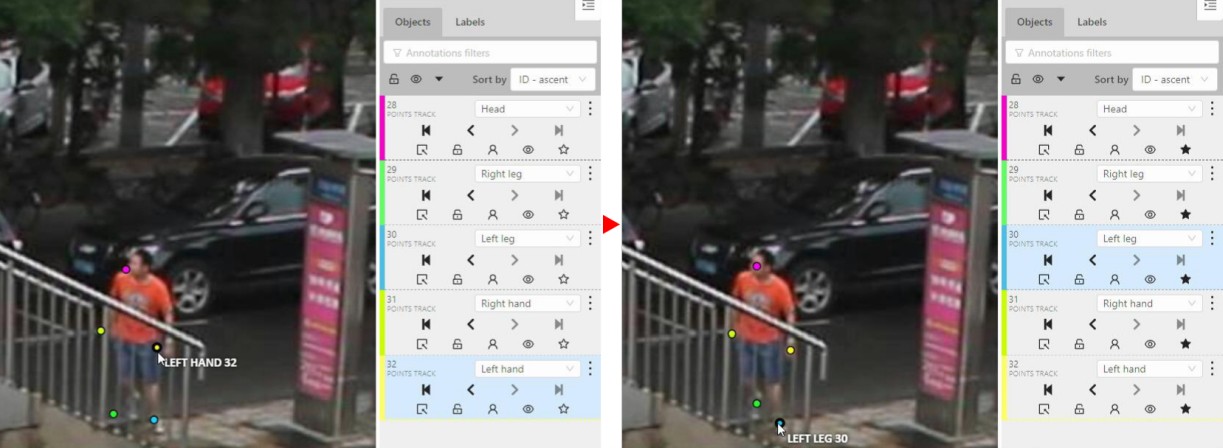
This way you’ll get linear interpolation using the Points.
It is used for road sign annotation etc.
First of all you need to select the ellipse on the controls sidebar.
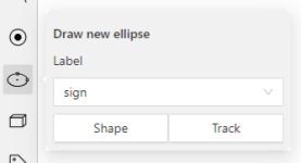
Choose a Label and click Shape or Track to start drawing. An ellipse can be created the same way as
a rectangle,
you need to specify two opposite points,
and the ellipse will be inscribed in an imaginary rectangle. Press N or click the Done button on the top panel
to complete the shape.
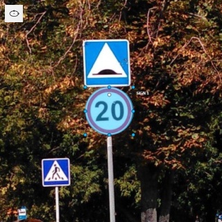
You can rotate ellipses using a rotation point in the same way as rectangles.
It is used to annotate 3 dimensional objects such as cars, boxes, etc… Currently the feature supports one point perspective and has the constraint where the vertical edges are exactly parallel to the sides.
Before you start, you have to make sure that Cuboid is selected
and choose a drawing method from rectangle or by 4 points.
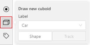
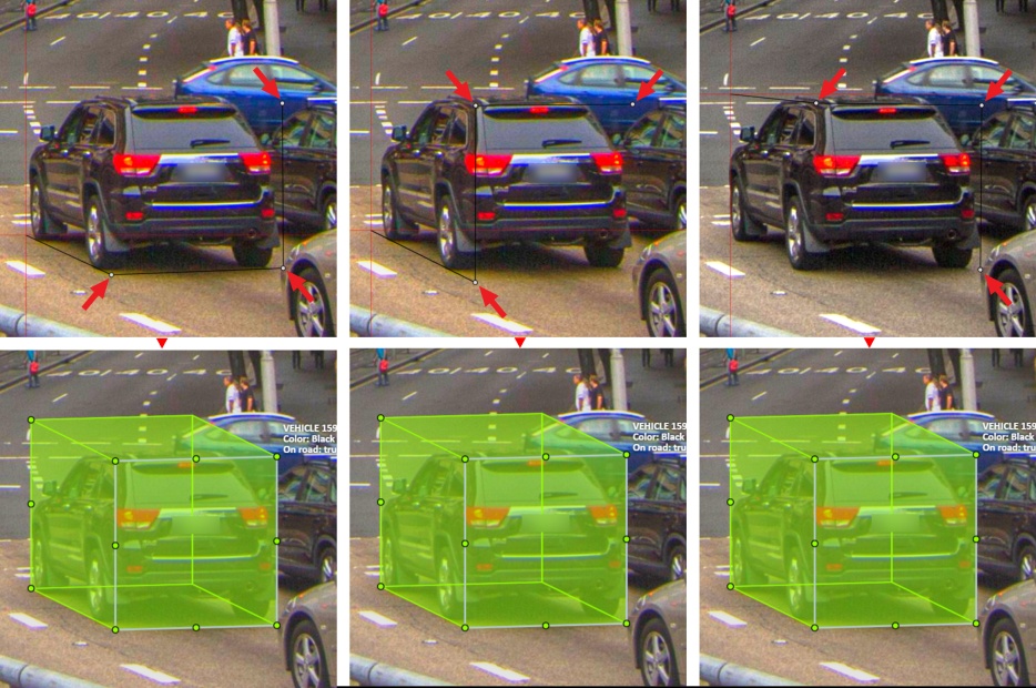
Choose a drawing method by 4 points and select Shape to enter the drawing mode.
There are many ways to draw a cuboid.
You can draw the cuboid by placing 4 points, after that the drawing will be completed automatically.
The first 3 points determine the plane of the cuboid while the last point determines the depth of that plane.
For the first 3 points, it is recommended to only draw the 2 closest side faces, as well as the top and bottom face.
A few examples:
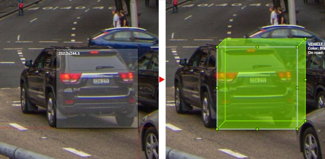
Choose a drawing method from rectangle and select Shape to enter the drawing mode.
When you draw using the rectangle method, you must select the frontal plane of the object using the bounding box.
The depth and perspective of the resulting cuboid can be edited.
Example:
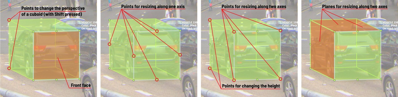
The cuboid can be edited in multiple ways: by dragging points, by dragging certain faces or by dragging planes. First notice that there is a face that is painted with gray lines only, let us call it the front face.
You can move the cuboid by simply dragging the shape behind the front face. The cuboid can be extended by dragging on the point in the middle of the edges. The cuboid can also be extended up and down by dragging the point at the vertices.
To draw with perspective effects it should be assumed that the front face is the closest to the camera.
To begin simply drag the points on the vertices that are not on the gray/front face while holding Shift.
The cuboid can then be edited as usual.
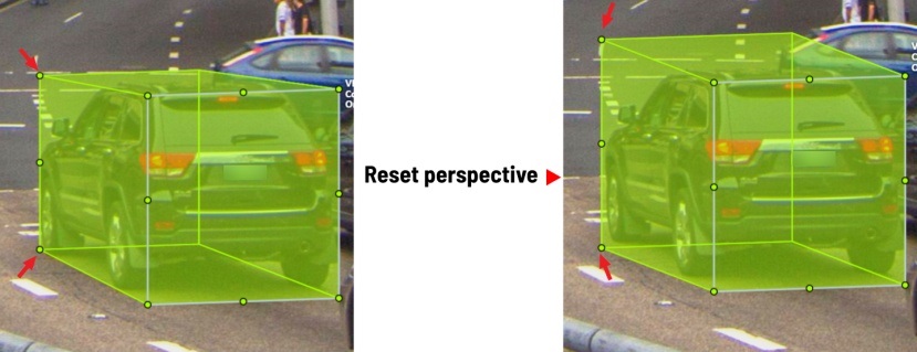
If you wish to reset perspective effects, you may right click on the cuboid,
and select Reset perspective to return to a regular cuboid.
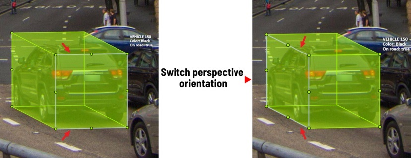
The location of the gray face can be swapped with the adjacent visible side face.
You can do it by right clicking on the cuboid and selecting Switch perspective orientation.
Note that this will also reset the perspective effects.
Certain faces of the cuboid can also be edited, these faces are: the left, right and dorsal faces, relative to the gray face. Simply drag the faces to move them independently from the rest of the cuboid.
You can also use cuboids in track mode, similar to rectangles in track mode (basics) or
In this guide, we delve into the efficient process of annotating complex structures through the implementation of Skeleton annotations.
Skeletons serve as annotation templates for annotating complex objects with a consistent structure, such as human pose estimation or facial landmarks.
A Skeleton is composed of numerous points (also referred to as elements), which may be connected by edges. Each point functions as an individual object, possessing unique attributes and properties like color, occlusion, and visibility.
Skeletons can be exported in two formats: CVAT for image and COCO Keypoints.
See:
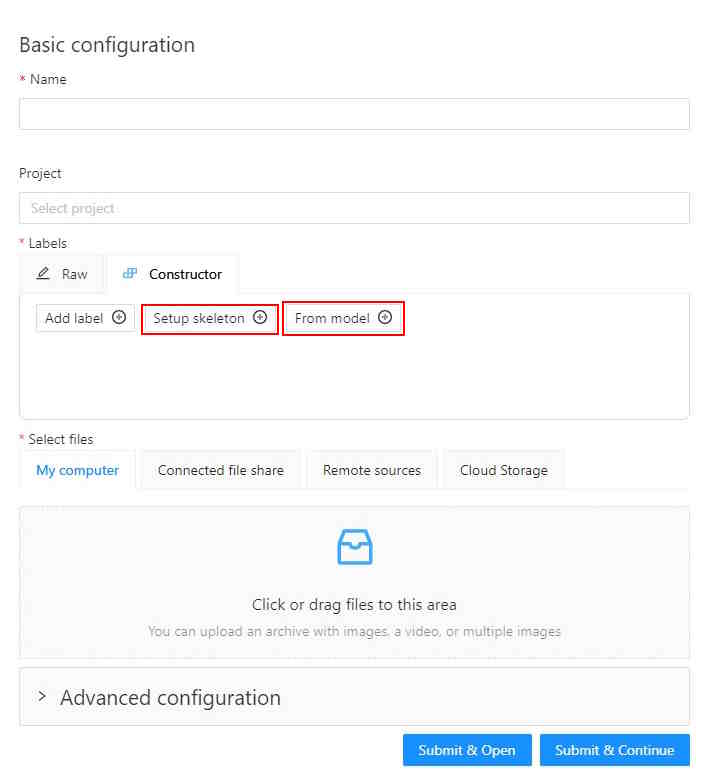
To start annotating using skeletons, you need to set up a Skeleton task in Configurator:
To open Configurator, when creating a task, click on the Setup skeleton button if you want to set up the skeleton manually, or From model if you want to add skeleton labels from a model.
The skeleton Configurator is a tool to build skeletons for annotation. It has the following fields:
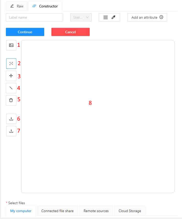
| Number | Name | Description |
|---|---|---|
| 1 | Upload background image | (Optional) Use it to upload a background image, to draw a skeleton on top of it. |
| 2 | Add point | Use it to add Skeleton points to the Drawing area (8). |
| 3 | Click and drag | Use it to move points across the Drawing area (8). |
| 4 | Add edge | Use it to add edge on the Drawing area (8) to connect the points (2). |
| 5 | Remove point | Use it to remove points. Click on Remove point and then on any point (2) on the Drawing area (8) to delete the point. |
| 6 | Download skeleton | Use it to download created skeleton in .SVG format. |
| 7 | Upload skeleton | Use it to upload skeleton in .SVG format. |
| 8 | Drawing area | Use it as a canvas to draw a skeleton. |
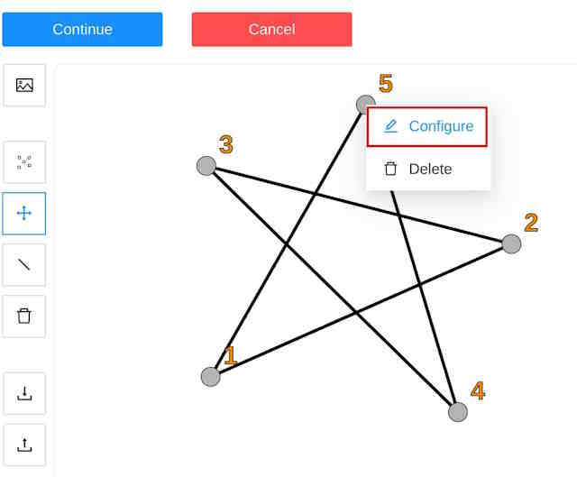
You can name labels, set attributes, and change the color of each point of the skeleton.
To do this, right-click on the skeleton point and select Configure:
In the opened menu, you can change the point setting. It is similar to adding labels and attributes of the regular task:
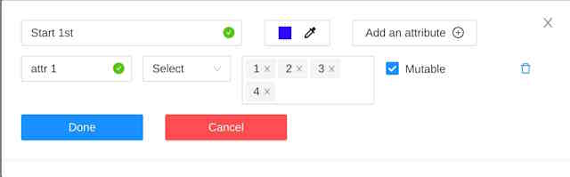
A Skeleton point can only exist within its parent Skeleton.
You cannot change the skeleton configuration for an existing task/project.
You can copy/insert skeleton configuration from the Raw tab of the label configurator.
To create the Skeleton task, do the following:
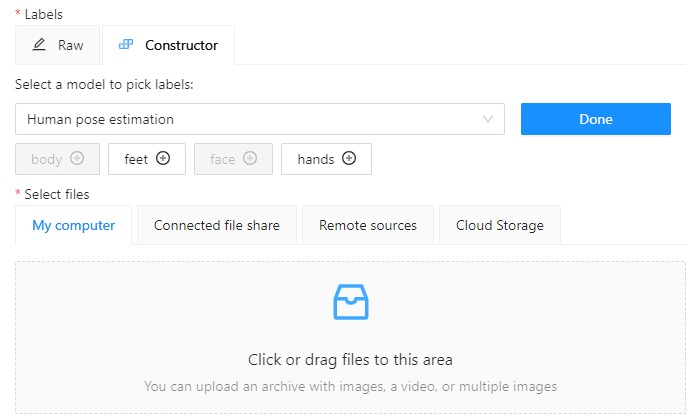
To add points from the model, and annotate do the following:
Open Basic configurator.
On the Constructor tab, click From model.
From the Select a model to pick labels select the
Human pose estimation model or others if available.
Click on the model’s labels, you want to use.
Selected labels will become gray.
(Optional) If you want to adjust labels, within the
label, click the Update attributes icon.
The Skeleton configurator
will open, where you can
configure the skeleton.
Note: Labels cannot be adjusted after the task/project is created.
Click Done. The labels, that you selected, will appear in the labels window.
Upload data.
Click:
To annotate with Skeleton, do the following
Open job.
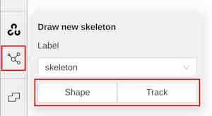
On the tools panel select Draw new skeleton.
Select Track to annotate with tracking or Shape to annotate without tracking.
Draw a skeleton on the image.
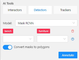
To automatically annotate with Skeleton, do the following
Open the job and on the tools panel select AI Tools > Detectors
From the drop-down list select the model. You will see a list of points to match and the name of the skeleton on the top of the list.
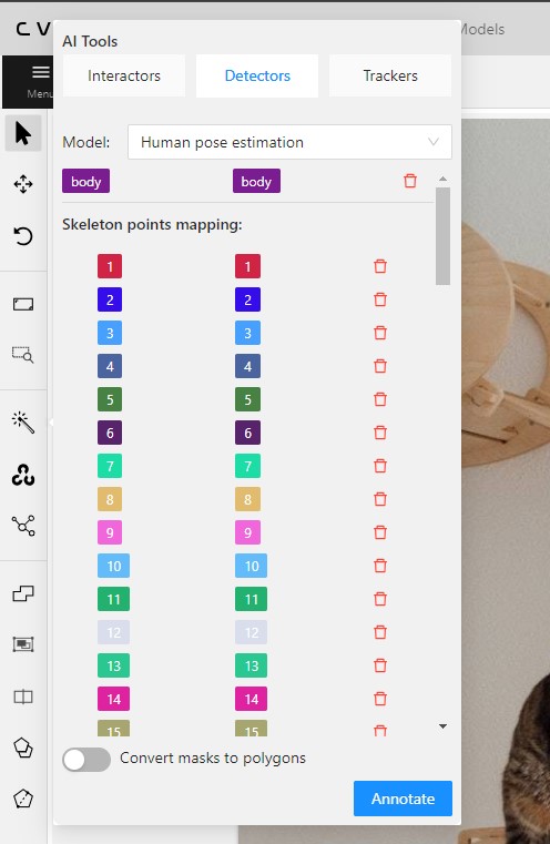
(Optional) By clicking on the Bin icon, you can remove any mapped item:
Click Annotate.
A drawn skeleton is encompassed within a bounding box, it allows you to manipulate the skeleton as a regular bounding box, enabling actions such as dragging, resizing, or rotating:
Upon repositioning a point, the bounding box adjusts automatically, without affecting other points:

Additionally, Shortcuts are applicable to both the skeleton as a whole and its elements:
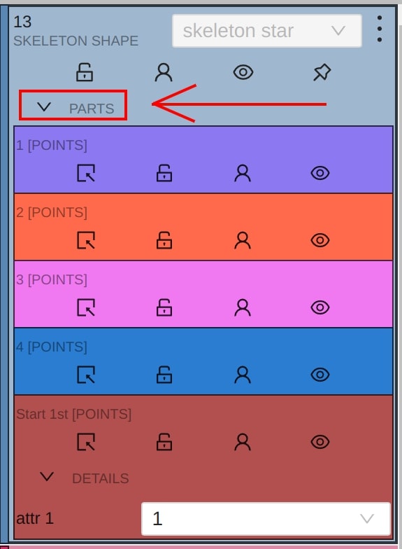
In CVAT, the sidebar offers an alternative method for setting up skeleton properties and attributes.
This approach is similar to that used for other object types supported by CVAT, but with a few specific alterations:
An additional collapsible section is provided for users to view a comprehensive list of skeleton parts.
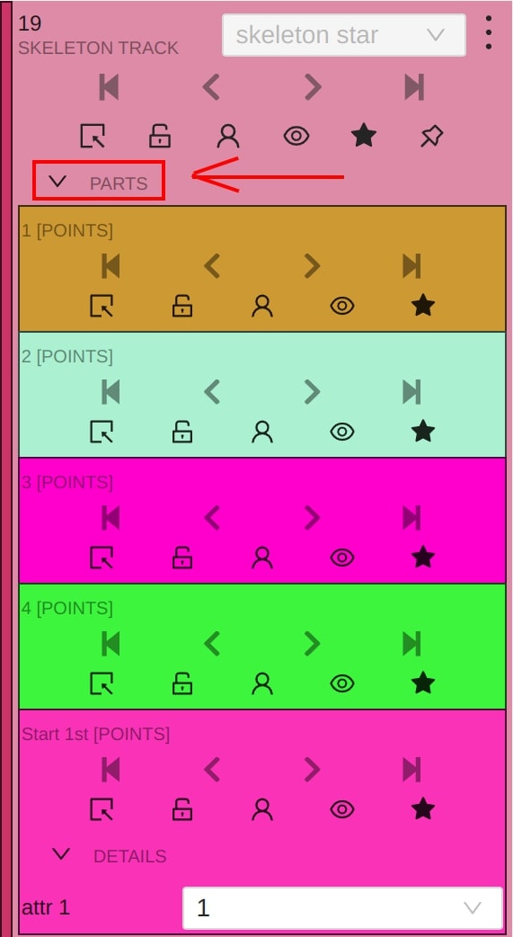
Skeleton points can have properties like Outside, Occluded, and Hidden.
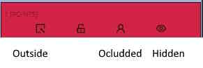
Both Outside and Hidden make a skeleton point invisible.
Outside property is part of annotations. Use it when part of the object is out of frame borders.
Hidden makes a point hidden only for the annotator’s convenience, this property will not be saved between different sessions.
Occluded keeps the point visible on the frame and usually means that the point is still on a frame, just hidden behind another object.
With a brush tool, you can create masks for disjoint objects, that have multiple parts, such as a house hiding behind trees, a car behind a pedestrian, or a pillar behind a traffic sign. The brush tool has several modes, for example: erase pixels, change brush shapes, and polygon-to-mask mode.
Use brush tool for Semantic (Panoptic) and Instance Image Segmentation tasks.
For more information about segmentation masks in CVAT, see Creating masks.
See:
The brush tool menu appears on the top of the screen after you click Shape:

It has the following elements:
| Element | Description |
|---|---|
| Save mask saves the created mask. The saved mask will appear on the object sidebar | |
 |
Save mask and continue adds a new mask to the object sidebar and allows you to draw a new one immediately. |
| Brush adds new mask/ new regions to the previously added mask). | |
 |
Eraser removes part of the mask. |
 |
Polygon selection tool. Selection will become a mask. |
 |
Remove polygon selection subtracts part of the polygon selection. |
 |
Brush size in pixels. Note: Visible only when Brush or Eraser are selected. |
 |
Brush shape with two options: circle and square. Note: Visible only when Brush or Eraser are selected. |
| Remove underlying pixels. When you are drawing or editing a mask with this tool, pixels on other masks that are located at the same positions as the pixels of the current mask are deleted. |
|
 |
Hide mask. When drawing or editing a mask, you can enable this feature to temporarily hide the mask, allowing you to see the objects underneath more clearly. |
 |
Label that will be assigned to the newly created mask |
 |
Move. Click and hold to move the menu bar to the other place on the screen |
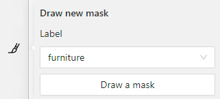
To annotate with brush, do the following:
From the controls sidebar,
select Brush ![]() .
.
In the Draw new mask menu, select label for your mask, and click Shape.
The Brush![]() tool will be selected by default.
tool will be selected by default.
With the brush, draw a mask on the object you want to label.
To erase selection, use Eraser
After you applied the mask, on the top menu bar click Save mask ![]()
to finish the process (or N on the keyboard).
Added object will appear on the objects sidebar.
To add the next object, repeat steps 1 to 5. All added objects will be visible on the image and the objects sidebar.
To save the job with all added objects, on the top menu, click Save  .
.
To annotate with polygon-to-mask, do the following:
From the controls sidebar,
select Brush ![]() .
.
In the Draw new mask menu, select label for your mask, and click Shape.
In the brush tool menu, select Polygon .
With the Polygon tool, draw a mask for the object you want to label.
To correct selection, use Remove polygon selection .
Use Save mask ![]() (or N on the keyboard)
(or N on the keyboard)
to switch between add/remove polygon tools:
After you added the polygon selection, on the top menu bar click Save mask ![]()
to finish the process (or N on the keyboard).
Click Save mask ![]() again (or N on the keyboard).
again (or N on the keyboard).
The added object will appear on the objects sidebar.
To add the next object, repeat steps 1 to 5.
All added objects will be visible on the image and the objects sidebar.
To save the job with all added objects, on the top menu, click Save .
Use Remove underlying pixels tool when you want to add a mask and simultaneously delete the pixels of
other masks that are located at the same positions. It is a highly useful feature to avoid meticulous drawing edges twice between two different objects.
![]()
You can convert AI tool masks to polygons. To do this, use the following AI tool menu:
For export, see Export dataset
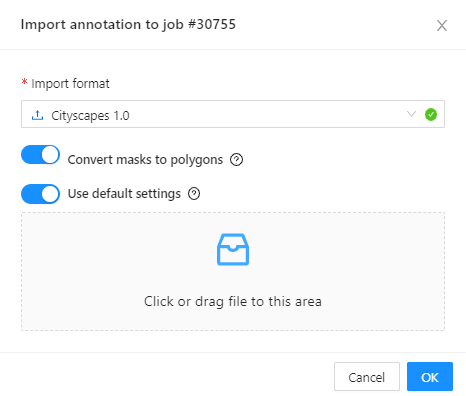
Import follows the general import dataset procedure, with the additional option of converting masks to polygons.
To use it, when uploading the dataset, switch the Convert masks to polygon toggle to the right:
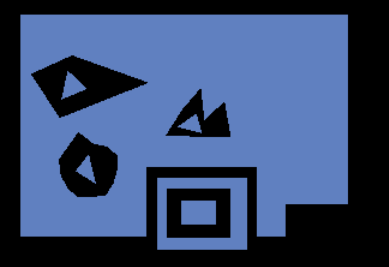
There are several shapes with which you can annotate your images:
Rectangle or Bounding boxPolygonPolylinePointsEllipseCuboidCuboid in 3D taskSkeletonTagAnd there is what they look like:


Tag - has no shape in the workspace, but is displayed in objects sidebar.
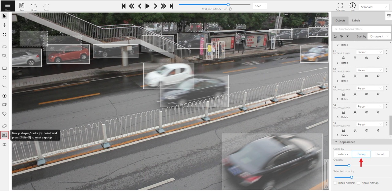
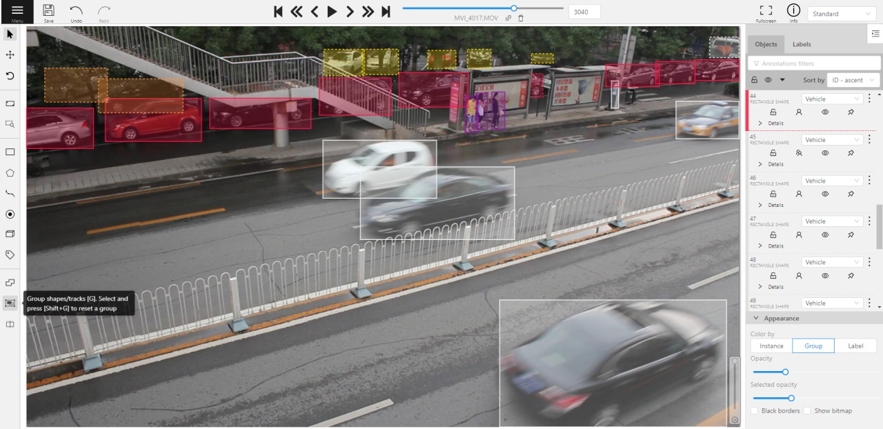
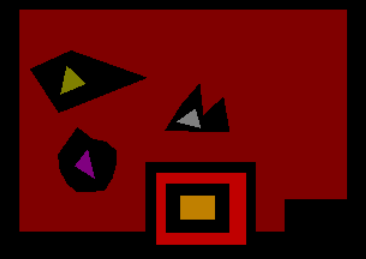
This feature allows us to group several shapes.
You may use the Group Shapes button or shortcuts:
G — start selection / end selection in group modeEsc — close group modeShift+G — reset group for selected shapesYou may select shapes clicking on them or selecting an area.
Grouped shapes will have group_id filed in dumped annotation.
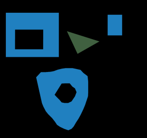
Also you may switch color distribution from an instance (default) to a group.
You have to switch Color By Group checkbox for that.
Shapes that don’t have group_id, will be highlighted in white.